Design for manufacture

Investment Casting Design Guide: 10 Essential Rules for Castable Parts

Investment casting responds strongly to wall sections, radii, draft, and how wax patterns and ceramic shells are built. Use these practical rules early in CAD to improve castability, reduce scrap, and hold tolerances without over‑machining.

10 essential rules ISO 8062 (CT4–CT7) Steel & stainless focus

Matson Foundry is ISO 9001 certified, applies ISO 8062 casting tolerance grades (CT4–CT7) as a common reference for precision castings, and has supplied investment castings worldwide since 2014.

Direct answer: The investment casting design guide covers 10 essential rules for creating castable parts, including uniform wall thickness (2.0–12.7 mm typical), proper draft angles (1–3° per side), fillet radii, wax pattern extraction, and ceramic shell limitations — helping engineers design parts that are manufacturable, cost-effective, and dimensionally accurate. Key entities: investment casting, lost-wax casting, wax pattern, ceramic shell, shrinkage, DFM, fillet radius, draft angle, ISO 8062.

Rule 1 — Maintain Uniform Wall Thickness

Why Uniform Walls Matter

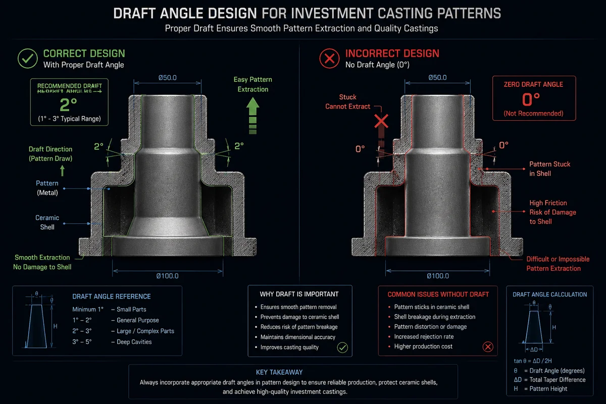
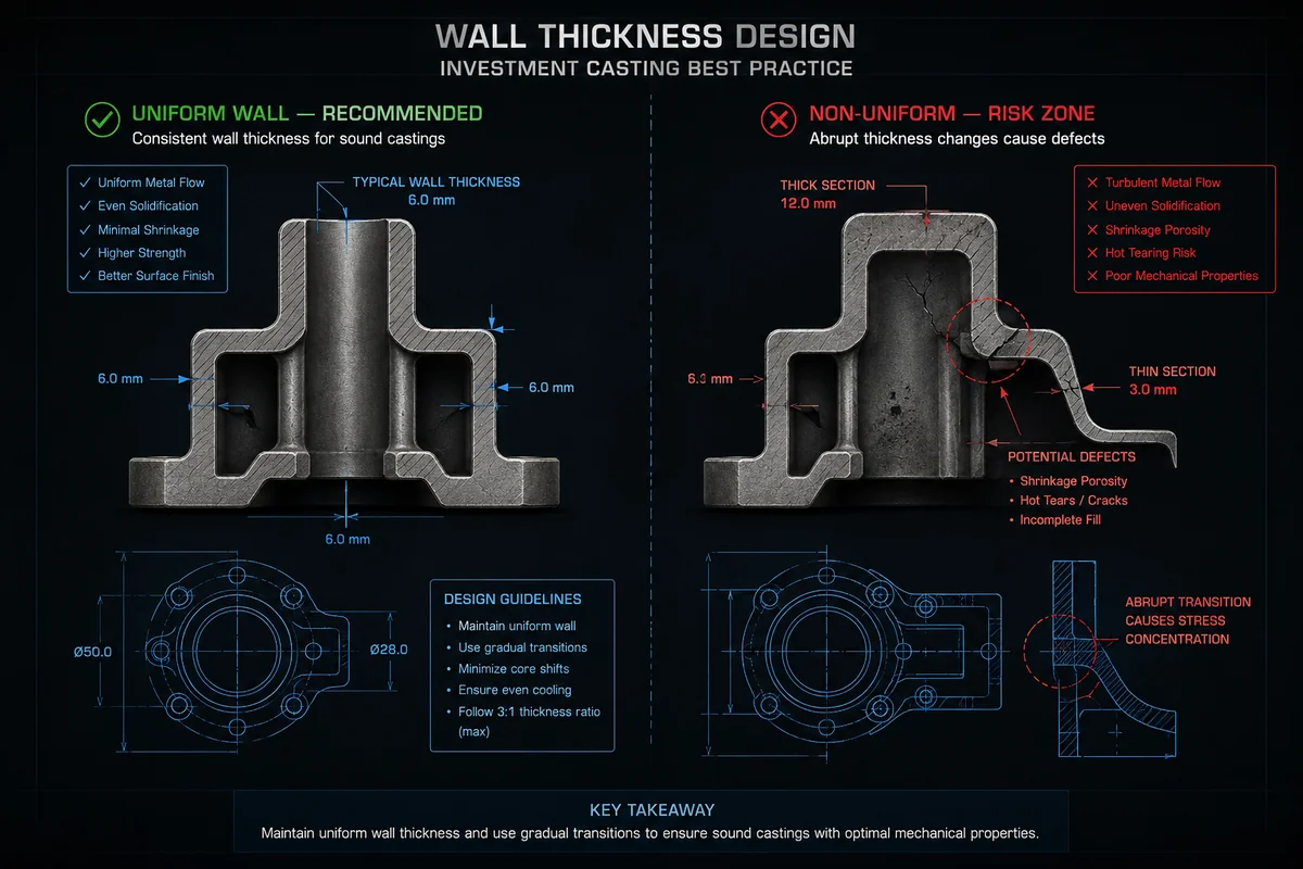
Uniform wall thickness helps metal flow evenly, cool at a controlled rate, and solidify without internal stress concentrations or shrinkage cavities. When walls vary too much in thickness, heavy sections cool more slowly than thin ones, creating hot spots that feed on surrounding metal and can leave shrinkage porosity. Non‑uniform sections also drive distortion during solidification and heat treatment, making it harder to meet dimensional tolerances. For investment casting, a practical "sweet spot" for most steels is typically in the 2.0–12.7 mm range, with most general‑purpose parts using 3–8 mm walls. Within a part, aim to keep neighboring sections within roughly ±20–30% of one another and transition thicknesses gradually.

Investment casting design guide — wall thickness guidelines chart for steel and stainless steel
Wall thickness targets and transitions strongly influence solidification and distortion risk.

Minimum Wall Thickness by Material

Different alloys have different fluidity and feeding behavior, so their minimum feasible wall thickness varies. As a rough guide under good foundry practice:

Material type Typical minimum wall (small areas) Practical recommended minimum (for stable production)
Carbon steel ≈ 2.5–3.0 mm 3.0–4.0 mm
Low alloy steel ≈ 2.5–3.0 mm 3.0–4.0 mm
Stainless steel ≈ 2.0–2.5 mm 2.5–3.5 mm
Aluminum alloys ≈ 2.0 mm 2.5–4.0 mm
Nickel superalloy ≈ 2.5–3.0 mm 3.0–4.5 mm

Very thin local features may be possible in special cases, but they typically come with higher scrap risk and tighter process control.

Common Wall Thickness Mistakes

Common mistakes include mixing very thin ribs (2–3 mm) with massive bosses (>20 mm) without proper fillets or transitions, and abrupt "steps" in thickness. These conditions lead to hot spots, shrinkage cavities near heavy sections, and distortion during heat treatment. Another frequent issue is designing large, flat, very thin plates that are prone to warping; in such cases, adding ribs or slightly increasing thickness can improve yield more than it increases weight.

Rule 2 — Add Proper Draft Angles

What Is Draft Angle in Casting?

Draft angle is the slight taper applied to faces parallel to the direction of pattern removal to allow the wax pattern to be pulled from its tooling without damage. Even though investment casting uses wax instead of metal cores, the wax still shrinks and grips the metal pattern, so zero‑draft walls can tear edges, distort features, or shorten tool life. Typical draft recommendations for investment casting wax patterns are around 1–3 degrees per side, more where surfaces are textured or deep.

Draft Angle Comparison by Casting Process

Draft requirements differ across processes because of tooling materials and pattern rigidity:

Investment casting draft angle design guide — comparison of investment casting vs sand casting vs die casting
Draft needs differ by process; investment casting still requires meaningful taper on wax pull directions.
Process Typical draft angle (general guidance)
Investment casting 1–3° per side on pull surfaces
Sand casting 2–5° per side (more for deep pockets)
High‑pressure die casting 0.5–2° per side on polished surfaces

Investment casting sits between die casting and sand casting: tooling is rigid like die casting, but wax behaves more softly than metal, so you still need meaningful draft. Where zero draft is absolutely necessary, plan for higher tooling cost and potentially more rework or scrap.

Rule 3 — Avoid Sharp Corners — Use Fillet Radii

Minimum Fillet Radius Guidelines

Sharp corners concentrate stress, obstruct metal flow, and become hot spots for shrinkage and cracks. For investment casting, use at least about 1.0 mm internal radius wherever possible, with 3.0 mm or larger preferred in structural or highly loaded regions. As a simple rule of thumb, aim for fillet radii around 25–50% of the adjacent wall thickness. External edges should also be eased slightly to aid shell building and reduce chipping risk.

How Fillet Radius Affects Casting Quality

Generous radii improve filling by guiding metal smoothly around changes in direction and reducing turbulence. They soften thermal gradients, which reduces hot tearing and shrinkage porosity near junctions. From a mechanical standpoint, larger fillets reduce stress concentration factors dramatically compared with sharp corners, improving fatigue performance. In practice, many casting defects found at "sharp corners" disappear after radii are increased and local section transitions are smoothed.

Rule 4 — Design for Wax Pattern Extraction

Wax patterns are produced in metal dies that must open along defined parting lines. This imposes constraints similar to other molded processes. Avoid undercuts relative to the die opening direction unless you plan for side actions, collapsible cores, or multiple pulls, which all increase tooling cost and complexity. Deep internal features may require separate wax cores that are assembled, adding labor and variability.

Plan parting lines early: align major ribs and flanges with the opening direction and place delicate details away from the die's "drag" surfaces. Where features like internal threads, blind slots, or complex undercuts are difficult to tool in wax, it is often better to cast a simpler boss or pad and machine the detailed feature afterward. Each time you insist on a cast‑in undercut or core slide, verify that the cost and risk are justified compared with a secondary operation.

Rule 5 — Consider Ceramic Shell Limitations

Shell Building Process Overview

In investment casting, wax patterns are assembled into trees, repeatedly dipped in ceramic slurry, stuccoed with refractory grains, and dried to build a strong ceramic shell. After dewaxing, metal is poured into this shell. The shell must survive handling, firing, metal hydrostatic pressure, and thermal shock. Thin, unsupported fins or very deep, narrow cavities can overstress the shell or prevent complete stucco coverage.

Internal Cavity Design Rules

As a practical rule, internal passage diameters of about 3 mm or larger are recommended for reliable shell formation and adequate flushing; smaller passages increase the risk of incomplete shell build or blockage. Depth‑to‑width ratios much above roughly 3:1 for blind cavities can be problematic, especially if there is no way for slurry and stucco to reach and drain properly. Long, thin "chimneys" or posts are prone to shell cracking and may require special support devices or design changes.

When designing complex internal geometries using ceramic cores, remember that the cores themselves are brittle ceramic parts. They need sufficient cross‑section for strength, generous fillets where possible, and adequate support at multiple points. Very thin core sections, sharp internal corners, or long, cantilevered features increase breakage risk and scrap.

Rule 6 — Account for Shrinkage and Solidification

Shrinkage Rates by Material Type

All metals shrink as they cool from pouring temperature to room temperature. Foundries compensate by scaling up wax patterns and tooling. Typical linear shrinkage ranges used for investment casting design are approximately:

  • Carbon steel About 1.5–2.5% linear shrinkage
  • Low alloy steel About 1.5–2.5% linear shrinkage
  • Stainless steel About 2.0–3.0% linear shrinkage
  • Aluminum alloys About 3.5–4.5% linear shrinkage

Exact values depend on alloy, section thickness, and process control, so the foundry will refine these numbers for each job.

Directional Solidification Principles

Beyond overall shrinkage, the way a casting solidifies determines where shrinkage porosity appears. Directional solidification means arranging the casting and feeders so metal freezes progressively from the thin, remote sections toward thicker sections and risers. In investment casting, proper gate and riser placement encourages metal to feed hot spots and minimizes isolated heavy sections.

Designers should avoid large isolated masses far from the gate or riser. Where such features are necessary, consider adding pads that can be fed effectively, or modifying the geometry to taper sections. Tooling is often adjusted (e.g., fillets, chills, local section changes) to guide solidification, but doing some of this at the CAD stage greatly helps yield and consistency.

Rule 7 — Plan Gating and Riser Systems

Gates and risers are usually designed by the foundry, but part geometry strongly influences what is possible. Preferred gate locations are on heavy, non‑critical surfaces where subsequent machining or blending is planned. Gate cross‑section size is chosen to provide smooth filling without excessive velocity; multiple smaller gates may be used to reduce turbulence on delicate features.

Risers (feeders) must have enough volume and thermal mass to remain liquid longer than the adjacent casting sections they feed. A common practice is to size risers so their module (volume‑to‑surface ratio) is greater than that of the attached section. Complex geometry may require multiple risers or chills to avoid internal shrinkage. The orientation of the part on the tree also matters: placing heavy sections upward facilitates feeding and minimizes the number of risers required.

Rule 8 — Set Realistic Tolerances

Linear Tolerance Capabilities

Investment casting delivers better dimensional control than sand casting, but it is not as tight as machining. As a typical rule, linear tolerances around ±0.1 mm per 25 mm of dimension (plus a base tolerance) are achievable on many features for well‑controlled parts. Small dimensions may hold tighter, while long spans or very heavy sections will need more generous limits.

Standards like ISO 8062 define casting tolerance grades (CT grades). Investment castings often achieve CT4–CT6 for many dimensions, depending on size and alloy. Large or complex parts may fall into looser grades.

Geometric Tolerances

Flatness, roundness, and concentricity tolerances depend on both process and geometry. Flatness on broad, thin plates is more difficult to control than on compact bosses. Concentricity of bores cast around cores depends on core stability and support. In general, moderate geometric tolerances are realistic, and very tight GD&T callouts should be reserved for surfaces that will be machined afterward.

Casting Tolerance vs Machining Allowance

A practical approach is to treat non‑critical surfaces as "as‑cast," applying casting tolerances, and to assign machining stock on critical features like precision bores, sealing faces, and datum surfaces. Trying to hold machining‑level tolerances on as‑cast surfaces greatly increases scrap and cost. Use machining stock carefully to avoid excessive removal (which wastes the benefit of near‑net shape), but provide enough (often 0.5–1.5 mm per side) to clean up after casting variation.

Rule 9 — Allow for Post-Processing

Machining Stock Recommendations

Most investment cast parts will have at least a few machined features, and our CNC machining services provide the post-casting finishing needed for critical datums and sealing faces. Typical machining stock allowances range from about 0.5 mm on small surfaces to around 1.5 mm on larger features or heavy sections. The allowance must cover casting dimensional variation, potential distortion during heat treatment, and fixturing misalignment. Tight‑tolerance datums may need slightly more stock to ensure reliable clean‑up.

Heat Treatment Dimensional Effects

Heat treatment can cause growth, shrinkage, or distortion depending on alloy and geometry. Austenitic stainless steels may move slightly, while hardenable steels can distort more significantly during quenching. Thin, asymmetric parts are especially vulnerable. When specifying final tolerances, consider heat‑treated condition and coordinate with the foundry on expected dimensional change. In some cases, intermediate machining (semi‑finish before heat treat, finish after) is advisable.

Surface finishing processes (shot blasting, polishing, coating) also remove or add small amounts of material and can change edge conditions. For cosmetic or sealing surfaces, ensure that finishing requirements and machining allowances are consistent.

Rule 10 — Design for Inspection

Inspection requirements should be considered during design, not after the fact. Radiographic (X‑ray) inspection needs clear access paths and uniform wall sections for good image quality; very thick‑thin combinations or overlapping sections can obscure defects. Ultrasonic testing requires surfaces that can be coupled with probes and adequate straight‑line paths through the material. Visual inspection and dimensional checks need line‑of‑sight and probe access.

Plan flat or lightly curved reference surfaces for dimensional datums and coordinate measuring equipment. Avoid hiding critical regions behind other features that block probe or X‑ray access. On drawings, clearly mark critical dimensions, critical areas for NDT, and surfaces where minor cosmetic imperfections are acceptable. This reduces ambiguity and helps the foundry focus process control where it matters most.

Investment casting design guide DFM checklist — wall thickness, draft angle, tolerances, post-processing
Print‑friendly DFM themes: geometry, tolerances, and post‑processing alignment.

Investment Casting DFM Checklist

Use this checklist to evaluate your design before sending it for quotation.

Wall Thickness & Geometry Checklist

  • Are primary walls within the recommended 2.0–12.7 mm range?
  • Are adjacent sections within about ±20–30% thickness of each other?
  • Are thickness transitions gradual (tapers/fillets) rather than abrupt steps?
  • Have you avoided large isolated heavy masses far from gates/risers?
  • Are flat, thin plates minimized or supported with ribs?

Tolerances & Specifications Checklist

  • Are linear tolerances aligned with typical investment casting capability (around ±0.1 mm per 25 mm where realistic)?
  • Are very tight tolerances reserved for features that will be machined?
  • Are geometric tolerances (flatness, concentricity, etc.) realistic for as‑cast surfaces and clearly specified?
  • Have you identified which surfaces are "as‑cast" vs "machined" on the drawing?
  • Is machining stock (0.5–1.5 mm typical) provided where needed?

Post-Processing & Inspection Checklist

  • Have you allowed for dimensional change from heat treatment in your tolerance scheme?
  • Are there accessible surfaces or datums for fixturing and measurement?
  • Are inspection methods (visual, dimensional, X‑ray, UT, etc.) compatible with the geometry?
  • Are critical regions for NDT clearly indicated for the foundry?
  • Are cosmetic requirements (surface roughness, blending, parting line treatment) clearly defined?

FAQs

What is the minimum wall thickness for investment casting in stainless steel?

Under good conditions, local stainless steel walls around about 2.0–2.5 mm are achievable, but most foundries recommend 2.5–3.5 mm for robust, repeatable production.

What draft angle is required for investment casting patterns?

A typical draft range is about 1–3 degrees per side on surfaces aligned with the wax pattern pull direction, with more draft for deep features or textured surfaces.

What tolerance can investment casting achieve per 25 mm?

A commonly cited capability is on the order of ±0.1 mm per 25 mm of dimension (plus a base tolerance), depending on size, alloy, and part complexity.

How much machining stock should be left on investment cast parts?

For most features, around 0.5–1.5 mm per side is typical, with smaller allowances for small parts and larger allowances for heavy sections or tight‑tolerance datums.

What is the typical shrinkage rate for carbon steel in investment casting?

Linear shrinkage for carbon steel is often in the range of about 1.5–2.5%, with exact values tuned by each foundry based on alloy and process.

Can investment casting produce internal threads or do they need to be machined?

Very coarse or simple external threads can sometimes be cast, but internal threads, fine pitches, and precision fits are usually machined after casting to ensure accuracy and reliability.

Start Your Casting Project

Send drawings or specifications — our engineering team responds within 24 hours with a detailed quote. For complete design-to-delivery support, explore our OEM custom casting service.